Tuesday, September 22, 2020

Halloween Trick-or-Treat Greeting Card

This Halloween card is similar to the scenes from my two previous blog posts.  The card is 5 inches x 5 1/2 inches.

Five scenes are combined to create the Halloween card.

The scenes are connected in a zig zag design.

The back of the card looks just as good as the front of the card.

I used 65 lb cardstock to make this card.

Here is the PDF.

Here is the .Studio file.

Here is the SVG.

Glue the tabs to the back of each scene. The back scene has the tab glued first and then the metallic paper is glued on top of it. The metallic oval is centered in the back of the this scene.


An Oval Slice Form Pumpkin With A Halloween Scene inside

I modified my previous blog post of a sphere Halloween slice form and made an oval pumpkin out of the outside slice form.  I added a stem, some leaves and a spiral curl to complete this new model.  This pumpkin slice form is mailable as the entire design does go flat when using the foldable slice form base design included in the files and shown in the previous blogpost https://papercraftetc.blogspot.com/2020/09/a-halloween-sphere-slice-form.html


Oval Slice Form Pumpkin with Halloween Scene Inside

I used 65 lb cardstock to make these slice forms.  The lettering on the round base that says "Happy Halloween" can be cut out from card stock, Foil Quilled or sketch penned.

Here is the PDF.

Here is the .Studio file.

Here is the SVG. 

The directions to make the slice form are in this blog post. https://papercraftetc.blogspot.com/2019/11/a-sliceform-snow-globe-with-ice-skating.html

The non-foldable base is glued at the seam and the base tabs are glued inside.

The brown slices for the stem are slid into the yellow stem that is protruding from the yellow center oval slice. Glue on the leaves and the two strips that have been curled to complete the model.


Monday, September 21, 2020

A Halloween Sphere Slice Form

This Halloween sphere slice form tells the story of three trick-or-treaters walking with their dog through a pumpkin patch who see a witch flying though the night sky.  

This slice form would make a nice Halloween display or a gift to someone special. Since slice forms can be folded flat, this diorama is suitable for mailing.  I have included two different types of bases.  One base can be made flat for mailing or the round base as a Halloween display in your home.

Halloween slice form with a base which will fold flat for mailing.

Another version of the mailable base.

Halloween slice form with a round base for a home display.

I used 65 lb cardstock to make these slice forms. The lettering on the round base that says "Happy Halloween" can be cut out from card stock, Foil Quilled or sketch penned.

Here is the PDF.

Here is the .Studio file.

Here is the SVG. 

The directions to make the slice form are in this blog post. https://papercraftetc.blogspot.com/2019/11/a-sliceform-snow-globe-with-ice-skating.html

I put a tea light in the round base as it is a little difficult to see all of the intricate cuts when black card stock is used. 

Tea light from the Dollar Tree in the base.

Illuminated scene with a tea light in the base.

Check out my next blog post which uses the same scenery and is made into a pumpkin slice form. https://papercraftetc.blogspot.com/2020/09/a-oval-slice-form-pumpkin-with.html

Tuesday, September 1, 2020

A STEM Project: Optical Illusions Using the Hyperduino

The optical illusion platform and discs from the previous blogpost, https://papercraftetc.blogspot.com/2020/09/a-stem-project-spinning-discs-which.html can be attached  to the motor on the Hyperduino. In this blogpost, I describe how to make the presentation box to house the Hyperduino and program it with Snap for Arduino.


Hyperduino presentation box with the optical illusion platform attached.

The Hyperduino operating the Optical Illusion Disc.


Disclaimer: 

- Adult supervision should be exercised when using the Hyperduino.

- This project involves a motor which could cause a fire. Do not operate unattended.


Here is the PDF.

Here is the .Studio file.

Here is the SVG.


Make the Hyperduino Presentation Box

Apply glue to the two center tabs as shown above.

Adhere the two sides pieces at the dotted line. Crease all of the dotted lines to form a box.

Apply glue to the top tab as shown. Adhere to form a triangle.  These triangles form the support structure for the box.

Apply glue and form the next triangle below.

Notice this creates a right angle and makes a sturdy support column for the box.

Repeat for the other side.

Apply glue as shown to the side that does not have a hole in the middle.  The triangular area on each side of this tab needs to remain free of glue. Apply glue to the two tabs to make the box.

Make the box by sliding the corners together so that the angled corner is visible. Adhere the glued tab. The vertical tab slides into the area that was not glued as noted above. In the photo above, it should look like the top left corner. Repeat for the right side.
The motor assembly components. Bend the motor strap as shown above.

Align the motor so that the shaft is in the middle of the hole. Insert the motor strap on one side of the motor and glue it down.  Insert the other side of the motor strap.

Glue the motor strap down.  

Apply glue to the square.  Notice that I used a lot of small dots of glue.  This piece needs to adhere correctly to the corresponding piece which is the top of the presentation box.

Adhere the top of the box as shown above.  Make the final support triangle by applying glue as shown.  The triangular corners of this tab need to be free of glue.

Remove the backing off of the yellow foam on the left.

Attach it to the orange plastic base.

Apply four Glue Dots in the four corners.

Adhere the orange base to the presentation box.

Insert the Hyperduino. The Hyperduino is not attached in any way.  You might want to use a Glue Dot to adhere it to its base if you want to make it transportable. 

Apply a Glue Dot to the plastic strap which is seen in the middle of the above photo but don't attach it to anything until you close the box.  The side tab will slide above the motor.  Adhere the motor Glue Dot at this point making sure that the motor shaft is centered in the hole. Again, I did not glue the corners so that the Hyperduino can be removed for other purposes.

Make the corners of the box by sliding the tabs.

View of completed presentation box.

Attach the motor cables as shown. Push in the orange rectangle and insert the pin. 

Cut out the platform pieces.

Apply glue to the tab.

Adhere the tab flat and then make it into a tube.

Insert the tube into the larger of the two discs and glue the tabs down.

Insert the other end of the tube onto the smaller disc.

Apply glue to the tabs on the tube.

Adhere the tabs down

Wait for the glue to dry.

Apply Glue dots to the large disc.

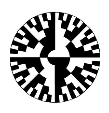
Adhere one of optical illusion discs to the platform.

Apply a Glue Dot to the axle of the yellow motor and then insert the platform onto the Hyperduino presentation box.

Program the Hyperduino with the above code in Snap for Arduino.  Alter the value of the speed from 75 up to 255.  The higher the value, the faster the disc will rotate.


A STEM Project: Spinning Discs Which Create Optical Illusions

Optical Illusion Discs

What is reality? Do our eyes see the world accurately?  Our vision interprets the world for us but it doesn't always perceive what is really there.  Optical illusions prove this fact.  Our eyes trick our brain to see things that are not there.  In this blog posting, I have included 20 different discs that can be spun to create different optical illusions. I have also included four discs that can be colored to create your own optical illusions. Try coloring different sections of the circle with different colors.  Increase and decrease the section sizes.  Experiment to find interesting color combinations and ask others to view your optical illusions to find out if they perceive things differently.

Here is the PDF.  I cut the platform from 65 lb. cardstock (110 lb. cardstock can also be used). The optical illusion images were printed on ordinary copy paper.

Here is the .Studio file. I cut the optical illusion platform with the Silhouette software.  I used scissors to cut out the discs from the PDF file.  It is not necessary to have a perfect circle as it is time consuming to print and cut each page individually. If you do want a perfect circle, use registration marks on each page, print the page and then cut that page with the Silhouette software.

Here is the SVG.


To make the optical illusion platform:

Cut out the platform pieces.

Apply glue to the axle tab as shown above.

Fold the tab flat to adhere the glue and then make it into a tube.

Insert the tube into the large circle and glue down the tabs. Allow the glue to dry before proceeding.

Insert the other end of the tube into the small circle circle as shown.  Apply glue to the tabs.

Adhere the tabs down with tweezers.

Completed platform.  Allow the glue to dry before using the platform.

Apply some Glue Dots to the platform.

Adhere one of the optical illusion platform.

Insert the pointed end of a pencil into the tube.

Spin the optical illusion disc by rotating the edge of the circle. 

Here are some observations about the optical illusion discs.

Spinning Spirals 
Rotate in one direction and the spirals seem to expand. Rotate in the opposite direction and the spirals seem to contract.  If you shift your gaze to another object, it will appear to expand if your spiral was shrinking or shrink if your spiral was expanding.  This phenomenon is known as the aftereffect. Your brain  and eyes can not react quickly enough to stop the action.
Spinning Spirals 
Spirals spin in opposite directions.  When you stop the disc, the spirals appear to pulsate.
Colors will appear in spinning bands.
In 1838, a scientist named G.T. Fechner discovered that when a circular disc with black and white lines were spun, imaginary colors appeared. He initially thought he would just see shades of gray. These effects are called Fechner lines. Scientists believe that your brain can not process the black and white images quickly enough. Your brain gets mixed up and believes that colors are present.

As the disc spins, the colors may not appear if the disc is not spinning fast enough or the light in the room is not sufficient or too bright. There are many factors which effect your eyesight and different people may see it differently because of the way their eyes focus.

Benham's Top 
Colors will appear as bands. When spun clockwise, the inner band is red, the next is green, yellow and the outer band is blue. Spun counter clockwise, starting from the center, blue, yellow green and red may be seen.

Newton's Disc
Colors will fade to grayish white when the disc is spun.
Colors will fade to yellow when the disc is spun.

Stereokinetic Effect
The rings rotate around a different axis resulting in spatial depth.


Try all of the optical illusions because "seeing is not always believing."