Friday, November 15, 2024

Oval Slice Form Pumpkin with Thanksgiving Scene Inside

Oval Slice Form Pumpkin with Thanksgiving  Scene Inside
To see the individual slices of the Thanksgiving scene, I recommend looking at the PDF file below.

The Thanksgiving scene can rotate as there is a gear in the base of the design.

I  used Neenah brand 65 lb Champagne Pearl metallic cardstock from Office Depot.  The lettering on the round base that says "Happy Thanksgiving" can be cut out from card stock, Foil Quilled or sketch penned.

Here is the PDF. 

Here is the .Studio file.

Here is the SVG. The file goes beyond the viewable area.  Zoom out to see the entire file.

The directions to make the slice form are in this blog post.https://papercraftetc.blogspot.com/2020/10/a-birthday-slice-form-sphere-that.html


The brown slices for the stem are slid into the yellow stem that is protruding from the yellow center oval slice. Glue on the leaves and the two strips that have been curled to complete the model.


Wednesday, November 13, 2024

A Pumpkin Picking Diorama for Fall


A Pumpkin Picking Diorama for Fall

The diorama depicts a boy and girl picking pumpkins in a farm. The little girl is picking a pumpkin to place I the boy's cart.  The little boy is pushing a cart of pumpkins. A family of deer is in the distance with a barn and windmill embellishing the scene.

Eight double thickness tabs keep the diorama scenes together.

Pretty paper is glued to the front of the first scene.
The tabs slide into the sides of the scenes.

Here is the PDF file. I  used Neenah brand 65 lb Champagne Pearl metallic cardstock from Office Depot and a sheet of "Wild Field" DCWV paper from Joanns. I recommend using a new blade and overcut to cut out this design as the intricate pieces might not cut correctly.

Here is the .Studio file.

Here is the SVG. The file goes beyond the viewable area.  Zoom out to see the entire file.

A Pretty Pumpkin Picking Diorama for Fall


Monday, November 11, 2024

A STEM Project: Comparing Three Different Methods of Coding a Sine Wave


Coding a Sine Wave in TurtleStitch Using the Sine Wave Equation y = a sin(Fx)


 Sashiko design called Hokusai

After coding the Sashiko design called Hokusai,  Cynthia Solomon challenged me to code a sine wave with just Arcright/Arcleft.  While the sine wave is not a circle, the arc commands can emulate the sine wave in small segments with adjustments made by a turn block.

In the following TurtleStitch program https://www.turtlestitch.org/run#cloud:Username=Elaine&ProjectName=Sine%20Wave%20Equation, I created three routines to make a sine wave. 

I used the following equation to code the sine wave.
  

Sine Wave Equation Code

y = a sin(Fx)

where:

a is the amplitude - makes the wave taller or shorter

F  is the frequency - how close the waves are together

This code creates an exact replica of a sine wave.


Arcright/Arcleft Code

This code uses arcright/arcleft to make the sine wave.

No calculations were made, just visual clues were used to code the sine wave. I coded this by using the original sine wave and then tracking the course of the curve with the turtle.  I used a different pen color to illustrate the arc's path. With trial and error, using different values of arcs and turns I created this sine wave.

The red curve is the calculated sine wave equation and the blue curve is the arcright/arcleft. You will notice the the blue curve is not an exact replica of the original because it is difficult to achieve the exact path with trial and error.


Turns and Moves Code

This code uses Turns and Moves to make the sine wave. I broke up the code into four sections so that you could see the receptive nature of the code.

No calculations were made, just visual clues were used to code this sine wave. I coded this by using the original sine wave and then tracking the course of the curve with the turtle.  I used a different pen color to illustrate its path. With trial and error, using different values of turns and moves, I created this sine wave.

The red curve is the calculated sine wave equation and the green curve is the turn/moves. Notice the green curve is not an exact replica of the coded "Sine Wave" because it is tedious to follow the path of the  original sine wave with trial and error.


Comparing the Three Methods of Coding a Sine Wave
While all three sine waves look similar, only one of these waves is exactly correct.  
The red sine wave is the coded sine wave equation. The blue and green sine waves are an approximation.  

It is also interesting to see the number of blocks that each method has used to create the sine wave.  The first column is the sine wave equation.  The second column is the arcright/arcleft blocks.  The third column onward is the turn and move blocks. 

By comparing the length of each code, you can see that the coded sine wave equation is half the length of the arcright/left code. The arcright/arcleft blocks are one-fourth the length of the turn/move blocks. The coded sine wave equation is one-eighth the length of the turn/move blocks. While the arcright/arcleft blocks simplify the code,  the coded equation is the shortest in length.

In conclusion, I think it is very interesting to compare and contrast the three coding methodologies.  It shows that there are multiple ways to achieve a goal when accuracy doesn't count. When precision is required, coding with equations is the simplest and most accurate method of coding in TurtleStitch.

Saturday, November 2, 2024

A STEM Project: Coding a SIne/Sinusoidal Wave In TurtleStitch

The pattern above is similar to a Sashiko design called Hokusai.
This pattern was created in TurtleStitch using different sine/sinusoidal wave orientations.

 
The difference between a sine wave and a sinusoidal wave is a sine wave oscillates in a smooth repetitive pattern centered at zero across the x-axis, with a regular phase and amplitude.
The sine wave equation is y = sin(x)

A sinusoidal wave has a general shape of a sine wave but it could either follow a sine or cosine function or any shifted version of these functions. The sinusoidal equation is y = a sin(Fx - p) + d

In the following TurtleStitch program, I created a program where you can compare different types of sine/sinusoidal waves.

Using the sinusoidal equation, y = a sin(Fx - p) + d, I created the Sashiko design called Hokusai.

Here is a link to my Hokusai TurtleStitch program.

Saturday, September 21, 2024

A Paper Jigsaw Puzzle Stand

A Paper Jigsaw Puzzle Stand

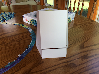
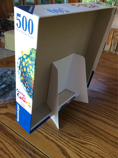
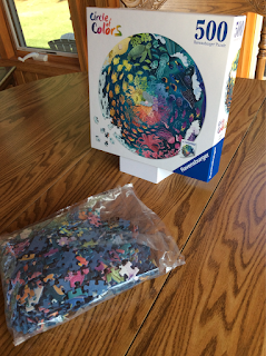
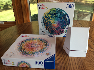
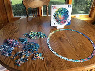
The Paper Jigsaw Puzzle Stand holds the box top for easy viewing.

I love jigsaw puzzles.  Did you know that there are jigsaw competitions who compete to see who is the fastest puzzler? I haven't joined any yet but I am trying to improve my speed.  I can do a 300 piece puzzle in approximately one hour. There are some puzzlers who can do a 500 piece puzzle in under 30 minutes!  I don't think I will ever be able to compete with that time.  This week there was a world competition in Spain sponsored by the puzzle company, Ravensburger. https://www.worldjigsawpuzzle.org I am amazed at the times of the competitors.

In this blog posting, I created a paper puzzle stand for the jigsaw box top. I saw some plastic stands online for approximately $15 but I was too cheap to purchase one.  I created this one instead. I hope you all can use one.  My paper jigsaw puzzle stand helps when viewing the design on the box top. 


The Paper Jigsaw Puzzle Stand holds the box at a nice angle.


Instead of having to prop up the box top at a right angle or have it lie flat on the table.

I recommend using 110 lb  cardstock for the puzzle stand.  As an alternative, cut the design twice using 65 lb. cardstock and glue them together to create a sturdy stand. I used a tape runner to glue the two pieces of paper together, using a watery glue like Elmer's causes the paper to warp.

Here is the PDF if you want cut out the puzzle stand with scissors. Print the design on cardstock and then cut it out. 

Here is the .Studio file for the Silhouette paper cutter.

Here is the SVG for all other electronic paper cutters like the Cricut.


My strategy is to sort all of the jigsaw pieces by color and then do the edge of the puzzle.

Hope everyone has fun puzzling!


Saturday, August 10, 2024

A STEM Project: Making a 16 x 16 inch Pillow Using Nine Squares of TurtleStitched Adinkra Embroidery Panels

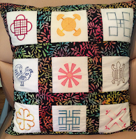
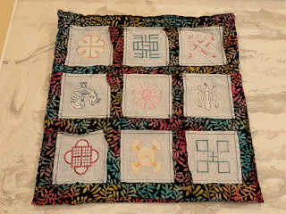
A 16 x16 inch Pillow Using Nine Squares of TurtleStitched Adinkra Embroidery Panels

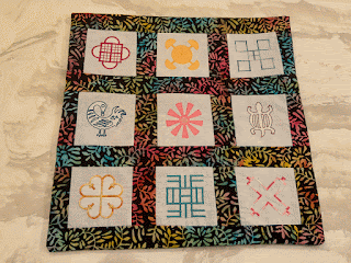
Adinkra are African symbols which represent different concepts, proverbs or aphorismsNine of these Adinkra designs were used to create this 16 x 16 inch pillow. I recreated these designs by coding them and embroidering them using TurtleStitch.  Here are my coded Adinkra designs in TurtleStitch. https://www.turtlestitch.org/projects/search/adinkra

When TurtleStitching the design for this pillow, I coded each design so that each would be no bigger than 2 1/2 x 2 1/2 inches.  Once embroidered, each of the nine designs were cut to create nine,  4 x 4 inch squares.


Materials Needed To Make a 16 inch x 16 inch pillow

9 - 4 x 4 inch TurtleStitch embroidered squares
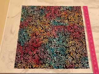
1/2 yard backing fabric
16 x16 inch Pillow Form

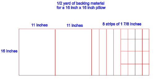
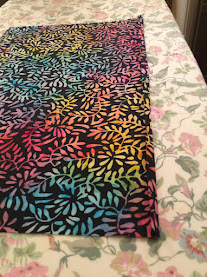
Cutting Layout - Cut out the strips using the cutting diagram below for the backing fabric


The result of the cuts will be: 

- Two strips of 16 x 11 inches
- Eight strips of 16 x 1 7/8 inches of which four of the strips are cut further to create sixteen strips of 4 x 1 7/8 inches  

Please note: The final measurement of the pillow is 15 1/2 x 15 1/2 inches.  This measurement allows for a plumper pillow.  


Sew the Squares Together 

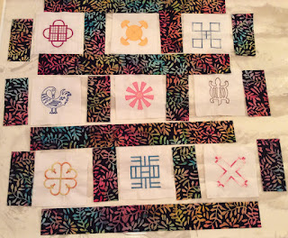
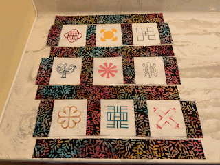
Arrange the strips of fabric around the nine TurtleStitched squares.

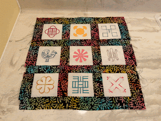
Using a 1/4 inch seam allowance, sew the 4 x 1 7/8 inch strips to the sides of the squares as shown above. Repeat for all rows.

Using a 1/4 inch seam allowance, sew the four 16 inch x 1 7/8 inch strips to the rows of three squares.

My 1/4 inch seam allowance was not exact so I evened up the 16 inch square by cutting the excess fabric around the edges. Set this piece aside.

Sew the Back Panels of the Pillow

Fold the 16 x 11 inch piece of fabric under a 1/4 inch on the 16 inch long side. Repeat to make another 1/4 inch fold and sew an 1/8 inch seam.
Repeat for the second piece of 16 inch by 11 inch fabric.

Place the two 16 x 11 inch pieces of fabric with the seams overlapping so that the backing fabric is a 16 x 16 inch square. The right side of the fabric is facing upward.

Place the embroidered 16 x 16 inch square on top of the back panels. Sew the four sides of the square using a 1/4 inch seam allowance.

Turn the fabric right side out and insert the pillow form to complete the pillow.

The meaning of the Adinkra designs starting at the top left of the pillow are: 

Abusua Pa - A symbol of family unity, kinship ties, and family support.

Akoma Ntoso -  understanding and agreement, harmony within communities.

Nsaa -  It is a symbol of excellence, genuineness, authenticity

Sankofa -   if you forget and you go back to get it, there is nothing wrong with it.

Ananse Ntentan -  means spider web. a symbol of wisdom, craftiness, creativity, and the complexities of life.

Denkyem -   means “crocodile.” It is a symbol of adaptability, cleverness

Name Due -  Symbol of God's presence and protection

Nea Onnim -  a symbol of knowledge, life-long education and the continued quest for knowledge.

Abab -  It is a symbol of strength, seat of power, authority, and magnificence.

Sunday, July 21, 2024

A STEM Project: Making Four Different Iris Mechanisms Each With A Different Number Of Blades

Making Four Different Iris Mechanisms Each With A Different Number Of Blades

An iris mechanism is one of the components of a camera.  The blades in the center of the mechanism open and close together to expose light to the underlying film.  In this blog posting, I will make four different iris mechanisms each with a different number of blades. My iris mechanism consists of three main parts a base plate with a handle, blades, and a blade ring. Paper tabs are used to attach the blades to the assembly. When the handle on the base plate is moved, the iris opens and closes.

I will explain how to assemble a three blade iris mechanism. The assembly of the four, five and six blade iris mechanisms are exactly the same but with an additional blade.

Iris Cutting Files

Here are the files to make the iris mechanism.  I have three versions of the files.  The first is a PDF where you can cut out the pieces with scissors.  The second file is for the Silhouette and the third file is all other electronic paper cutting machines. 

Materials needed. - Glue Dots or glue and 65 lb cardstock

Here is the PDF. 

Here is the .Studio file for the Silhouette.

Here is the SVG. The file goes beyond the viewable area.  Zoom out to see the entire file.

Making the Iris Mechanism

Make the blades by creasing the tabs and placing a dot of glue in the center of the tab.  Insert the tab into the top of the blade.  On the other side, insert the tab at the bottom of the blade in the opposite direction resulting in one inward facing tab and one outward facing tab. The orientation of the tabs are the same for all blades. 

 Repeat for all of the blades.

Insert the top tab of the blade into the base plate with a handle. The tab will be inserted from the bottom of the base plate. Splay the tab outward.   Repeat for all of the blades.

Flip the base plate over.  Align all of the blades into a circle.  The first blade will be on top of the second blade and the second blade will be on top of the third blade and so on.  The last blade will be on top of the first blade.

Lay the blade ring with the ring tabs oriented to the right and the curve facing left as shown above. Insert the blade tabs into the holes in the blade ring and splay the tabs outward. 

Make sure the iris mechanism works before attaching the decorative rings. Open and close the mechanism a few times. It might be a little tight to begin with but it should loosen with repeated opening and closings.

Flip the iris mechanism over. Apply glue or Glue Dots to the six tabs of the blade ring. (The photos show seven tabs.  A tab was eliminated after these photos were taken.) I like Glue Dots better because it allows the mechanism to move a little when the iris mechanism opens and close. Lay the decorative ring on top of the iris mechanism. 

Loosely fold over the tabs.  Adhere all of the tabs.

Flip the iris mechanism over. Apply glue to the areas away from the blade tabs on the blade ring.  If glue is applied by the tabs, the mechanism will not work. 

Adhere the decorative ring.

Open and close the iris repeatedly.  

This will loosen the tightness of the iris.

Saturday, June 1, 2024

A STEM Project: A Paper Microscope with One and Two Lens

A Paper Microscope with One and Two Lenses

Components of a Paper Microscope

A One Lens Eyepiece and a Two Lens Eyepiece with a Spacer Tube for the Objective Lens, A Magnetic Base for the Microscope and a Specimen Slide which Attaches with a Magnet


In a previous blog posting https://papercraftetc.blogspot.com/2024/05/a-stem-project-making-simple-paper.html, I coded an entire paper microscope using a glass marble as the lens in TurtleStitch and I explained the steps that were required to program the design. In this blog posting, I will replace the glass marble with one lens on the eyepiece tube and then construct another eyepiece tube for two converging lenses. The eyepiece tube will be held upright with two supporting structures. I also modified the base of the microscope to include magnets so that the specimen slide and the microscope base will be automatically aligned when the corresponding magnets are placed together. I got the idea of using magnets for the specimen slide from Foldscope, https://foldscope.com I thought it was ingenious that they used a magnet to align the lens and the specimen slide together.

My focus of building this paper microscope is to give the building blocks necessary to create a microscope  for different lenses of various focal lengths.  While I am giving you values for my particular lens, I am supplying the TurtleStitch code to modify the lengths of the components, so that you can create your own microscope to your particular needs.

A one lens microscope is called a simple microscope. It is similar to a magnifying glass. A two lens microscope uses two lenses to compound or multiply the level of magnification. The first microscopes were made by putting two or three magnifying glasses together.


TurtleStitch Code

Here is the TurtleStitch code for the components of a microscope with one lens. https://www.turtlestitch.org/run#cloud:Username=Elaine&ProjectName=Components%20For%20a%20Microscope%20With%20One%20Lens

Here is the TurtleStitch code for the components of a microscope with two lenses. https://www.turtlestitch.org/run#cloud:Username=Elaine&ProjectName=Components%20For%20a%20Microscope%20With%20Two%20Lens

Here is the TurtleStitch code for the microscope base and support beams. https://www.turtlestitch.org/run#cloud:Username=Elaine&ProjectName=Microscope%20Support%20Beams%20and%20Base

Here is the TurtleStitch code for the microscope box.

Here is the TurtleStitch code for the specimen slide.

Types of Lens Used

The three lens that I used are from Thor Labs, https://www.thorlabs.com I used a 12.7 mm lens with a focal point of 50 mm (Thor Labs - AC127-050-A) for the eyepiece of the single lens microscope.

For the double lens microscope, I used a 12.7 mm convex lens with a focal point of 50 mm for the eyepiece (Thor Labs -  LB1844) and a 12.7 mm convex lens with a focal point of 25 mm for the objective (Thor Labs - LB1844) which is the lens that you place next to the specimen. The focal length of the eyepiece lens is about 160 millimeters or 6.29 inches. The focal length of the objective lens is about 25 millimeters or about .984 inches.


Microscope Cutting Files

Here are the files to make the paper microscope.  I have three versions of the files.  The first is a PDF where you can cut out the pieces with scissors.  The second file is for the Silhouette and the third file is all other electronic paper cutting machines. 

Materials needed. - Glue Dots, three lenses as explained previously, magnet paper and a tea light

Here is the PDF. It is recommended to use 65 lb black cardstock because a dark background allows for more contrast which will allow you to see your specimens better. (I used white cardstock for design purposes only.)

Here is the .Studio file for the Silhouette.

Here is the SVG. The file goes beyond the viewable area.  Zoom out to see the entire file.


Make the Box   -  Only one box is necessary to make the microscope with one lens or two lenses because the telescoping eyepiece tube design is the only thing that is replaced with the new lens and a lens spacer.

Crease the box top as shown above and apply glue to the two tabs on the sides. Repeat for the other side of the box. Insert the tea light into the bottom of the box and affix it with a Glue Dot (not shown).  I recommend offsetting the tea light a little from center because you do not want direct light when viewing a specimen.  Close the box with the tea light inside.

Make the Specimen Holder

Crease the specimen slide and apply Glue Dots to the two tabs of the specimen slide to adhere them together.

Make the Eyepiece Tubes - Three tubes will be made, two eyepieces tubes and an eyepiece support tube.

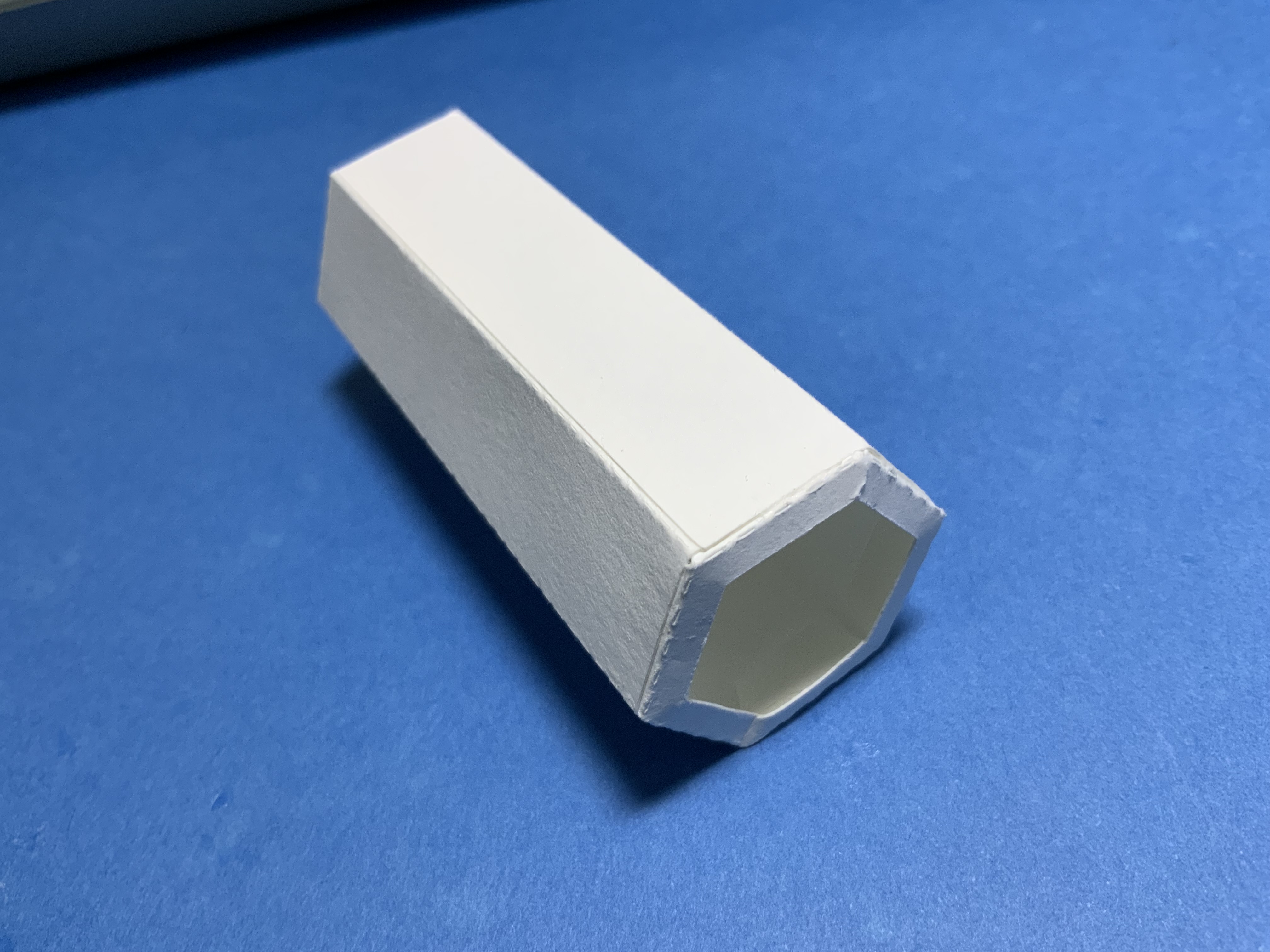
Crease the hexagonal eyepiece tubes. Apply glue to the eyepiece tube and the eyepiece support tube at the tabs. Precision gluing is required so that the tubes will telescope.

The eyepiece tube can be folded flat so that the glue will adhere properly. (Shown in the photo above on the left.)  Do not leave it in this position for too long as glue might have entered the center of the tube and adhere it together. Once each tab has adhered, make the tubes into a hexagonal tube.

Place each eyepiece tube into the eyepiece support tube.  Slide the shorter tube back and forth at least twenty times to make sure that the tubes will telescope properly. Test for the second eyepiece tube.


Apply glue to two lens holders on the six tabs and insert it into each side of the eyepiece tube. Repeat for the second eyepiece tube.

The ends of the eyepiece tubes will look as shown above.


Make the Lens Holders For All Three Lenses - One for the 'One Lens Microscope' and two for the eyepiece and objective lens of the 'Two Lens Microscope'

Crease the two lens holder strips into a circle that are two different sizes - one longer than the other.
Apply glue to the two tabs and adhere at the dotted line on the strip.

Glue the lens holder strip onto the lens circle. Try to center the lens holder strip on the circle. Repeat for the other side.
Insert the lens into the smaller side. Apply glue to the inner edge of the smaller side.

Adhere the two sides together. Write the lens value on the lens circle so that the lens do not get mixed up.  Repeat for the other two lens. 


Assemble the Eyepiece Tube for the 'One Lens Microscope'

For the one lens microscope, apply glue to the top of the lens circle.

Adhere it to the lens holder of the eyepiece tube. 

Assemble the Eyepiece Tube for the 'Two Lens Microscope'

For the two lens microscope, apply glue to the top of the eyepiece lens circle.

Adhere the eyepiece lens to the top of the eyepiece tube.

Make the spacer for the objective lens by creasing the spacer into a circle, applying glue to the tab and adhering the tab.
Glue the lens circle to the bottom of the spacer.

Apply glue to the top of the spacer as shown.

Adhere the objective lens to the spacer.

Glue the spacer to the eyepiece assembly which has the corresponding eyepiece lens as shown above.
Please notice the placement of the two lenses as this is a fixed length.


Make the Support Beams for the Base of the Microscope

Crease the support beams and apply glue as shown above.

Fold the beams into two triangles.  Apply glue to one side of the triangle as shown above and adhere it together.  A square beam is then formed. Repeat for the second beam.

Insert the tabs of the beams into the base.

Glue the tabs to the base as shown above.

Apply glue to the side of the beams facing one another. 

Adhere the eyepiece support tube to the sides of the beams.

Add Magnets to the Base of the Microscope and the Specimen Slide

Apply glue to the four corners of the microscope base. Adhere magnet pairs (eight magnets are used) to each of the four corners. A magnet pair is two magnets which are attracted to one another and are attached. I recommend orienting all of the magnet pairs in the same direction of magnetism before gluing.

Apply glue to these four magnet pairs and adhere them to the box base.  Allow the glue to dry.  When the glue is dry, four magnets will be attached to the microscope base and four magnets will be attached to the box base. 

Align the specimen template to the specimen holder. Two magnet pairs (four magnets) need to be glued
 to the left and right squares in the template. Apply glue to the two magnet pairs. Adhere this specimen slide with the magnets to the bottom of the microscope base by centering the square and round holes.  Once the glue is dry, remove the template and throw it away.  It is no longer needed. 

The placement of the twelve magnets should look as above.

Turn on the tea light and add a specimen to the specimen holder. 

Attach the specimen slide to the microscope base aligning the magnets.

Align the magnets on the four corners of the microscope base to the box base.


Using the 'One Lens Microscope'


Slide the eyepiece tube into the eyepiece support tube with the lens oriented to the bottom of the tube. 

The specimen is now ready to be observed by sliding the eyepiece tube up and down until the specimen is clearly in view.

Calculations for the 'One Lens Microscope' for a achromat lens with a 50 mm focal length

-Image Distance to Lens


Magnification


A Graph of Magnification Sensitivity
The graphics shows that at a distance from the specimen to the lens of 50.8 mm (approximately two inches), the specimen is in focus.


Using the 'Two Lens Microscope'


 Slide the eyepiece tube into the eyepiece support tube with the eyepiece lens oriented on the top and the objective lens with a spacer at the bottom.

The specimen is now ready to be observed by sliding the eyepiece tube to the bottom of the eyepiece support tube.  The length of the focal point is fixed when using the two lens. I found that it was difficult to get the specimen aligned in the microscope for viewing.  I flipped over the specimen slide so that the magnets did not attract.  I was then able to focus the specimen. 


Calculations for the 'Two Lens Microscope' with Two Converging Convex Lens 

Eyepiece Focal Length is 50mm - Objective Lens is 25 mm

-Image Distance from the objective lens to the specimen is 40 mm 


Total Magnification


Conclusion

I liked the one lens microscope better because the specimen was easier to view and to focus.  The  specimen on a two lens microscope was hard to see because the lengths of the lens are set on the eyepiece due to the calculations of the lens formula. Since everyone's eyesight is different, it is hard to fine tune the image when the distances are fixed.