Simple Components of a Marble Microscope
Eyepiece tube, a specimen slide and a glass marble lens
Simple Microscope Assembly Using a Glass Marble
In a previous blog posting, I created a simple microscope using a clear glass marble from the Dollar store. I designed and coded parts of the microscope in TurtleStitch. https://papercraftetc.blogspot.com/2024/04/a-stem-project-making-simple-microscope.html
In this posting, I coded the entire microscope design in TurtleStitch and I will explain the steps that were required to program the design.
Coding a Three Dimensional Design in TurtleStitch To Be Cut and Joined in Paper
Coding a three dimensional object appears at first to be a daunting task because of the third dimension. It is easy to code a square in two dimensions but how do you code a square box with a top that slides into the bottom? It is best to examine a square box like this and look at its structure. How was it made? Each side of the box needs to be coded. Squares are easy to code and then the joining of the sides needs to be taken into account.
To create a simple square box, all the side lengths will be the same. The square that is in the middle of the above figure needs to be dashed lines because solid lines are cut lines and dashed lines are fold lines.
When the inner square is changed to dashed lines, the image should look like this.
The only thing that is left to do is to make tabs for the box. The tabs are needed so that the corners of the box can be joined at this location with glue. I like to make my tabs from .25 to .5 inches wide depending on how big the box will be.
Two tabs are joined at the sides of the squares in the upper and lower squares.
For the simple microscope box, the sides of the box need to be shorter. In the example above, the four outer squares were adjusted to the same height to make the box with a shorter height.
The design is now ready to be coded in TurtleStitch. This design is called a net because it is a design which can be cut and folded to create a solid shape.
When designing in paper, the size of the object must be taken into account because of the constraints of the medium. Paper comes in different sizes, usually 8 1/2 x 11 inches. The above photo shows another variation of a box. This box had to be made differently because the top of the box is bigger. The sides are cut separately and then are attached to the top of the box.
Basic Building Blocks in TurtleStitch
There are some basic building blocks that are needed to code a three dimensional design in paper. A 3D design requires tabs and folds to join the different paper parts together. They are an edgefold block, a dashed line block and a one inch block.
Edgefold Block
The edgefold block is used to create a tab strip for gluing parts together. The tabbed strip can be made with three variations of teeth - rectangular, trapezoidal or triangular teeth and a variable number of teeth.
https://www.turtlestitch.org/users/Elaine/projects/Edgefold%20Block
In the example shown above, a 2.5 inch x .5 inch strip is created with eight trapezoidal shaped teeth spanning the strip with the orientation of the teeth going downward.
Dashed line Block
The dashed line block is used to create a fold line for bending the paper at the tabs.
https://www.turtlestitch.org/run#cloud:Username=Elaine&ProjectName=Dashed%20Line%20Block
In the example shown above, a 1 inch dashed line is created with 5 dashes per inch.
One inch Block
A one inch block is necessary to convert the design to the correct size when it is cut using an electronic paper cutting machine as the size is not preserved in the export process. This file should be exported as a DXF file in TurtleStitch. It should then be resized in the electronic paper cutting software using the one inch block as reference.
https://www.turtlestitch.org/run#cloud:Username=Elaine&ProjectName=One%20Inch%20Block
The one inch block is used for reference once the file has been opened with the electronic paper cutting software to be cut. The one inch block needs to be moved away from the design by placing a value in steps to inches block.
Please Note: I have consolidated all of these blocks into one TurtleStitch program called "Basic Components of 3D Papercrafting".
https://www.turtlestitch.org/users/Elaine/projects/Basic%20Components%20of%203D%20Papercrafting
Here are the three links to the TurtleStitch code for the Simple Microscope.
1). Simple Microscope Box
https://www.turtlestitch.org/run#cloud:Username=Elaine&ProjectName=A%20Simple%20Microscope%20Box
2). Simple Microscope Components
3). Specimen Slide
Coding the Simple Microscope Box
The microscope box is a square box with four sides that are attached with four tabs.
The top and bottom of the box are similar. The difference between them is that the bottom is 98 % smaller than the top of the box. This allows for the box to slide into one another easily.
I created some custom blocks for the box because I wanted to simplify my code.
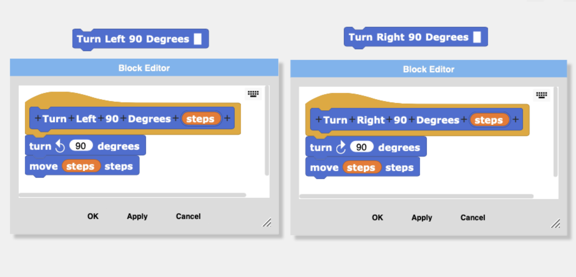
The blocks that I created are the Turn Left 90 Degrees and Turn Right 90 Degrees blocks. I combined a turn and move in each of these blocks. Using these blocks will cut coding down by 50% when these blocks are used.
The two sided edgefold block creates the side of the box and two tabs.
I also created a Box block which contains the code which creates the top of the box. To create the bottom of the box. The 'side' value is set to 98% of the top's value.
Calculate the center of the box to put a hole in it for the microscope light.
Once the box top is made, a hole is placed in the center by using the following calculations.
size of the side/2 = center point of square box
Once at the center of the box is determined, the radius of the circle needs to be subtracted to put the turtle in the correct position to construct the circle. The turtle needs to be pointing upward to construct the circle.
Image of the box top and bottom (one inch square not shown) that were created in TurtleStitch.
Coding the Simple Microscope ComponentsEyepiece tube (red) and the lens holder strips (blue) are coded like the Simple Microscope Box with the same blocks - edgefold, dashed lines, turn right and turn left blocks
The coding of the lens holder requires trigonometry to calculate the inner hexagon's side length.
The outer hexagon is made with the 'dash line' block and the 'edgefold' block using the hexagon length value of 0.555 inches.
To find the inner hexagon side length,
The side length of the inner hexagon is equal to the outer hexagon side length minus two times the opposite side of the triangle.
Find the hypotenuse.
And then the opposite side length of the triangle to move the turtle the inner side length distance.
Here is the code that calculates the hypotenuse and the inner side length of the hexagon.
The circle measurement for the lens circles were measured from the glass marble. The outer circle is approximately 0.45 inches and the inner circle is half of that measurement. The coding of the placement of the circles inside of one another is the same concept of the circle placed in the center of the box.
Coding the Specimen Slide
The specimen slide looks complicated to code but it is easy to see that only half of the slide needs to be coded because the image is mirrored.
The next thing to look at before coding is the shapes that make up the design. The circular cutouts are semicircles which are easy to code using the Arcright or Arcleft blocks. The rest of the design is right angles which are simple to code.
I did add a special feature in my Specimen Slide block code. I added a variable called 'scale'. I wanted to be able to vary the size of the specimen slide without changing my code.
To scale a design, the scale variable needs to be multiplied by the value of the movement of the turtle. The scale value must be multiplied each time a move is made. This is a tedious task if the scale value is added after the code has been made. It is a good idea to think about scaling before any code is written.
The design can be scaled in the electronic paper cutting software but it is nice to have the ability to code it. It is not always easy to get exact sizes in the electronic paper cutting software.
Directions to Cut the Box with the Silhouette or other any other electronic paper cutting machine.
Export the TurtleStich design as a DXF file.
The DXF file is then opened in the Silhouette software. The size of the one inch square is observed. The size of the entire file needs to be resized as the size is not preserved from one application to the other. Divide 1 by the size of the observed one inch square and then multiply by 100. Transform the entire file with the calculated percentage amount. Check the one inch square to see if it is now one inch. (The one inch square is no longer needed, and it can now be deleted.)
Simple Microscope Cutting Files
Here are the files to make the simple paper microscope. I have three versions of the files. The first is a PDF where you can cut out the pieces with scissors. The second file is for the Silhouette and the third file is all other electronic paper cutting machines.
Materials needed. - Glue Dots, Glass Marble and a Tea Light
Here is the PDF. I used 65 lb cardstock.
Here is the .Studio file for the Silhouette.
Here is the SVG. The file goes beyond the viewable area. Zoom out to see the entire file.
Make the Box
Crease the box top as shown above and apply glue to the two tabs on the sides. Repeat for the other side of the box. Insert the tea light into the box and affix it with a Glue Dot (not shown).
Apply Glue Dots to the two tabs of the specimen slide.
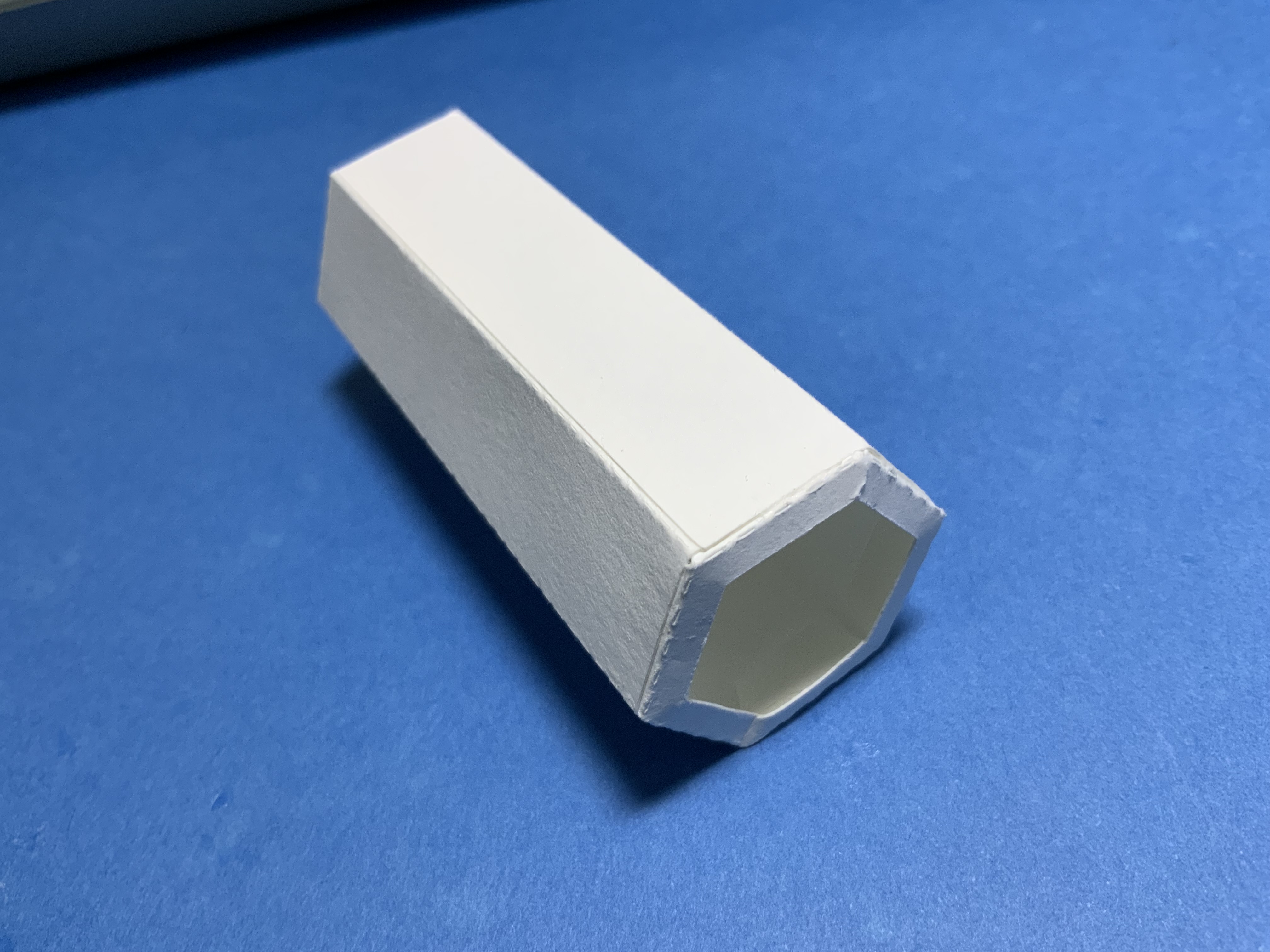
Make the Eyepiece Tube
Crease the tube and apply glue to the side tab. Shape into a hexagonal tube.
Apply glue to the lens holder on the six tabs.
Insert the lens holder into the eyepiece tube.
Make the Lens Holder
Crease the two lens holder strips into a circle.
Apply glue to the two tabs and adhere.
Glue the lens holder strip onto the lens circle. Repeat for the second one.
Insert the glass marble into the smaller side. Apply glue to the top edge of the larger side.
Adhere the two sides together.
Assemble the Viewing Platform
Insert the specimen into the specimen slide.
Assemble the simple microscope by placing the specimen slide on top of the lite box and then align the eyepiece tube in the center of the specimen slide to view the specimen.